ball mill schematic

Ball Mill; Principle, Working, and Construction » Pharmaguddu

Ball Mill; Principle, Working, and Construction » Pharmaguddu

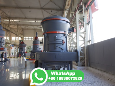
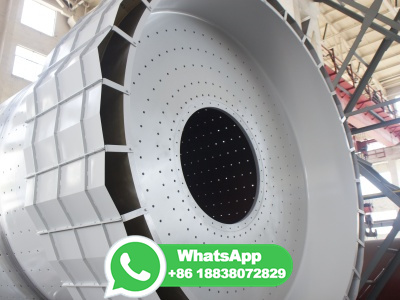
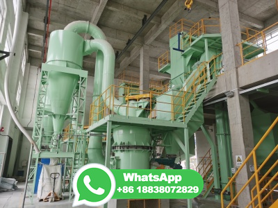
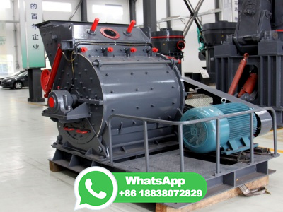
Attrition: Reduced the size of the materials when they colloid by heavy weight (Ball). Construction: The ball mill grinder consists following Parts: Cylinder: cylinder is made of a hollow metal that moves about its horizontal axis. the cylinder can be made of porcelain, metal, and rubber. the length of the cylinder slightly higher than its diameter.

Open Access proceedings Journal of Physics: Conference series IOPscience

Open Access proceedings Journal of Physics: Conference series IOPscience

The schematic diagram of the planetary ball mill disk and the vial . Absolute Velocity . The Absolute velocity of one ball leaving the wall is given by: (1) And subsequently the velocity of the ball in the vial with d. b. diameter, after hitting the inner walls of the vials can be expressed as follow .

How a Grate Discharge Ball Mill Works 911 Metallurgist

How a Grate Discharge Ball Mill Works 911 Metallurgist

How a Grate Discharge Ball Mill Works. Here I try to explain how ground slurry is discharged from a grate ball mill (or SAG). How it works is, the slurry flows across the grate as it would a screen panel. On the other side of the grate/screens are veins like a pump impeller. As the mill turns/rotates the slurry is "pumped" out and discharged.

1. Different types of ball mill: attrition mill, horizontal mill ...

1. Different types of ball mill: attrition mill, horizontal mill ...

Join for free. Download scientific diagram | 1. Different types of ball mill: attrition mill, horizontal mill, planetary mill, and the 1D and 3D vibratory mills from publication: "Mechanical ...

The working principle of ball mill Meetyou Carbide

The working principle of ball mill Meetyou Carbide

22 May, 2019. The ball mill consists of a metal cylinder and a ball. The working principle is that when the cylinder is rotated, the grinding body (ball) and the object to be polished (material) installed in the cylinder are rotated by the cylinder under the action of friction and centrifugal force. At a certain height, it will automatically ...

Schematic representation of various types of ball mills [30 ...

Schematic representation of various types of ball mills [30 ...

Download scientific diagram | Schematic representation of various types of ball mills [30] "Reprinted/adapted with permission from Ref. [30]. 1999, Royal Society of Chemistry (Great Britain)".

DIY Ball Mill Plans Homemade Rod Mill Drawing 911 Metallurgist

DIY Ball Mill Plans Homemade Rod Mill Drawing 911 Metallurgist

homemade ball mill plans. By this drawing, it is suggested that a typical homemade laboratory rod mill or ball mill might be fabricated from 20 cm (8 inches) diameter schedule40 type 316 stainless steel pipe and would be about 38 cm (15 inches) long.. The plans show stainless steel grinding rods for this size of mill may be a graduated charge from 25 to 10 mm diameter (1 inch to 1/2 inch) but ...

Ball milling: a green technology for the preparation and ...

Ball milling: a green technology for the preparation and ...

Ball milling is a simple, fast, costeffective green technology with enormous potential. One of the most interesting applications of this technology in the eld of cellulose is the preparation and the chemical fi modi cation of cellulose nanocrystals and nano bers. Although a number of studies have been reported fi fi

Ball Mill Grinding Theory Crushing Motion/Action Inside

Ball Mill Grinding Theory Crushing Motion/Action Inside

Open Circuit Grinding. The object of this test was to determine the crushing efficiency of the ballmill when operating in open circuit. The conditions were as follows: Feed rate, variable from 3 to 18 T. per hr. Ball load, 28,000 lb. of 5, 4, 3, and 2½in. balls. Speed,

Characteristics of open and closedcircuit grinding systems

Characteristics of open and closedcircuit grinding systems

The pulverizer used in this study was a continuous vibration ball mill and the classifier was a forced vortex type with secondary air injection. Fig. 2(a) shows the continuous vibration ball mill used in this study. The particles are pulverized by passing from the upside to the downside direction. Fig. 2(b) shows a schematic diagram of the ...

Making a Ball Mill : 4 Steps Instructables

Making a Ball Mill : 4 Steps Instructables

place the motor in the motor bay and hold down with a block of wood screwed to the bay walls. put the drive band on the motor, if you have done everything right it should be fairly tight, it has to be otherwise it will not drive the roller. now just wire up the switch and attach it to our computer cable and we are done! the dimmer switch can be used to control the speed of the ball mill, if ...

How to Make a Ball Mill: 12 Steps (with Pictures) wikiHow

How to Make a Ball Mill: 12 Steps (with Pictures) wikiHow

1. Fill the container with small metal balls. Most people prefer to use steel balls, but lead balls and even marbles can be used for your grinding. Use balls with a diameter between ½" (13 mm) and ¾" (19 mm) inside the mill. The number of balls is going to be dependent on the exact size of your drum.

Discrete element simulation of particle motion in ball mills based on ...

Discrete element simulation of particle motion in ball mills based on ...

The parameters of the particles and the ball mill, as well as the interaction parameters of particlesparticle and particlesball mill wall are shown in Table 5. Download : Download highres image (182KB) Download : Download fullsize image; Fig. 5. (a) Schematic diagram of the ball mill; (b) DEM model of the ball mill.

PDF ATTRITORS AND BALL MILLS HOW THEY WORK Robert E ... Union Process

PDF ATTRITORS AND BALL MILLS HOW THEY WORK Robert E ... Union Process

the mill. The common range of mill speeds is 65% to 80% of critical, depending on mill type, size and the application. The critical speed of a ball mill is calculated as divided by the square root of the radius in feet. The rotational speed is defined as a percentage of the critical speed. Smaller diameter mills

PDF Module7 unit3 NSNT Module 7 Ballmilling INFLIBNET Centre

PDF Module7 unit3 NSNT Module 7 Ballmilling INFLIBNET Centre

Ball mill is crucial to numerous industries as an equipment for producing extremely crushed materials, cement, refractory materials, fertilizers, glass ceramic, ore dressing of ferrous as well as nonferrous metals, etc. Ball mill can be used to grind ores and other materials which can be both wet and dry. On the

A schematic diagram of a planetary ball mill (crosssection).

A schematic diagram of a planetary ball mill (crosssection).

A schematic diagram of a planetary ball mill (crosssection). | Download Scientific Diagram Fig 1 uploaded by Y. T. Feng Content may be subject to copyright. A schematic diagram of...

Modelling of the HighEnergy Ball Milling Process

Modelling of the HighEnergy Ball Milling Process

this work, the highenergy planetary ball mill process is modeled using the software Automated Dynamic Analysis of Mechanical System MSC Adams [ 22 ]. Figure 2 illustrates a schematic of a highenergy planetary ball mill equipped with two cylindrical vials. The mill was powered by a kW electric motor.

Grinding Circuit Control Strategy 911 Metallurgist

Grinding Circuit Control Strategy 911 Metallurgist

Figure 4 is a schematic diagram of a ball mill/cyclone control system. This diagram shows the instrumentation and the calculated variables used in the control strategies. The prior detailed process analysis study produced two major conclusions: Reduce mill feed size Reduce ball charge size

Autogenous Grinding Semi Autogenous Grinding Circuits 911 Metallurgist

Autogenous Grinding Semi Autogenous Grinding Circuits 911 Metallurgist

ABC closed circuit, AutogenousBallMillCrusher. Another similar technique is the ABC open circuit where the crusher product feeds the ball mill rather than the autogenous mill. Crusher product is typical feed to a ball mill using large diameter balls but not much grinding of 2025 mm ore can be accomplished in an autogenous mill.

Mill Lubrication System | PPT SlideShare

Mill Lubrication System | PPT SlideShare

Parts of Ball Mill to be lubricated: Trunnion bearing Feed end Gearbox Trunnion bearing Dis. end Pinion : Ball Mill diagram. Motor 26. Gathered Data: This were the alarm gathered during my stay in the Mill. MILL ALARM DATE Diff. High Pressure Trunnion Feed End April 20, 2013 SAG Bearing Recirculation Oil Inlet Temp. High April 28, 2013 ...

Ball Mill Principle, Construction, Uses, Advantage, Disadvantage, and ...

Ball Mill Principle, Construction, Uses, Advantage, Disadvantage, and ...

C. Ball mill is an open system, hence sterility is a question D. Fibrous materials cannot be milled by ball mill. 10. What particle size can be obtained through ball mill? A. 20 to 80 mesh B. 4 to 325 mesh C. 20 to 200 mesh D. 1 to 30 mm. ANSWERS:1. Both B and C 2. Optimum speed 3. Longitudinal axis 4. Both 5. A 3 B 4 C 2 D 1 6 ...

How to design a Ball Mill Grinding Classification Circuits ...

How to design a Ball Mill Grinding Classification Circuits ...

You also need a rod mill work index to design a ball mill operating on a coarse feed, above about 4 mm. Q1: You design for a typical percentage of critical speed, usually 75% of critical. Then you iterate the mill diameter using a Morrell Cmodel or Nordberg equation to get the RPM that corresponds to 75% for that mill diameter.

AMIT 135: Lesson 6 Grinding Circuit Mining Mill Operator Training

AMIT 135: Lesson 6 Grinding Circuit Mining Mill Operator Training

AG/SAG mills can accomplish the same size reduction work as two or three stages of crushing and screening, a rod mill, and some or all of the work of a ball mill. Because of the range of mill sizes available, AG/SAG milling can often be accomplished with fewer lines than in a conventional rod mill/ball mill circuit. A diagram of types of AG/SAG ...

Materials Development Using HighEnergy Ball Milling: A Review ... MDPI

Materials Development Using HighEnergy Ball Milling: A Review ... MDPI

Highenergy ball milling (HEBM) of powders is a complex process involving mixing, morphology changes, generation and evolution of defects of the crystalline lattice, and formation of new phases. This review is dedicated to the memory of our colleague, Prof. Michail A. Korchagin (), and aims to highlight his works on the synthesis of materials by selfpropagating hightemperature ...

Schematic diagram of a ball mill. The balls make up the grinding media ...

Schematic diagram of a ball mill. The balls make up the grinding media ...

Schematic diagram of a ball mill. The balls make up the grinding media and drive rollers help to rotate the milling chamber. Source publication +3 Overview of milling techniques for...

Stirred Mill an overview | ScienceDirect Topics

Stirred Mill an overview | ScienceDirect Topics

Schematic drawing of an attrition ball mill. The attrition mill agitator rotates at speeds ranging from 60 rpm for production units to 300 rpm for laboratory units and uses media that range from 3 to 6 mm while ball mills use large grinding media, usually 12 mm or larger, and run at low rotational speeds of 1050 rpm.

PDF Design and Analysis of Ball Mill For Paint Industries IJSRD

PDF Design and Analysis of Ball Mill For Paint Industries IJSRD

Ball mill is vital equipment used in industries for mineral dressing, ore processing, fertilizers, paint industries, food and diary, pharmaceuticals and many others. In ball mills, ... Fig. 1: Mill and cover plate diagram B. Power Required To Operate The Ball Mill With Optimum Ball Charge[10]:

Process Control of Ball Mill Based on MPCDO Hindawi

Process Control of Ball Mill Based on MPCDO Hindawi

The flow diagram of the ball mill system is illustrated in Figure 1, including the ball mill, pump sump, hydrocyclones, and vibratory conveyor. Figure 1 . Flow diagram of the ball mill grinding process. The system dynamics are described as follows. During the grinding process, the raw ore is firstly sent into the ball mill mixed with water.

Inserting PID Schematic Symbols Autodesk Knowledge Network

Inserting PID Schematic Symbols Autodesk Knowledge Network

Click Schematic tab Insert Components panel Insert PID Components. Find; In the Insert Component: Piping and Instrumentation Symbols dialog box, click Equipment. In the PID: Equipment dialog box, click Ball Mill. Respond to the prompts as follows: Specify insertion point: Select to place the ball mill in the upper left corner of your drawing

دریافت اطلاعات بیشتر